WHAT ARE BIOFILMS AND WHY DO THEY MATTER? PART 2 – BIOFILM-RELATED PROBLEMS
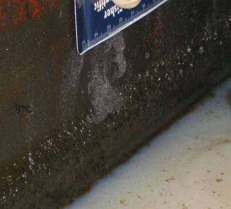
Biofilm at Metalworking Fluid Surface – Sump Wall Interface.
Biofilms Part 1 Recap
In my last What’s New article I wrote:
Biofilms can form on any surface that is in contact with water. In aqueous systems such as heat exchanger, potable water, firemain, containing water-miscible metalworking fluid, biofilms can coat >90 % of surfaces in contact with the fluid. In systems containing fuels, lubricants, or other fluids in which water is not normally miscible, biofilms typically develop in zones where condensate water accumulates.
Biofilms are complex structures comprised primarily of EPS. Microbes living in biofilm consortia resemble the cells of multicellular organisms. Physiologically, they can be quite distinct from genetically identical planktonic cells. Additionally, genetically identical microbes can differ physiologically based on their location within the EPS matrix. Due to the combined effects of microbial metabolic activity and EPS chemistry, the physicochemical environment within biofilms can be very different from that of the fluid with which it is in contact. Chemical gradients within biofilms contribute to microbiologically influenced corrosion (MIC).
In this article, I’ll review the types of biodeterioration damage that can be associated with biofilms. In particular, I’ll discuss:
- Biofouling
- Heat exchanger, heat transfer reduction
- Microbiologically influenced corrosion (MIC)
Biofouling
Biofouling is the unwanted accumulation of organisms, their excreted polymers (see EPS discussion in the May 2022 What’s New article), and entrained substances on surfaces. Although multicellular organisms, such as barnacles, can be part of biofouling communities, in this article I’ll focus on microbial biofouling. Figure 1 shows four examples of biofouling. Figure 1a is a fermentation unit’s transfer line. Biofouling contributes to finished product contamination and inhibits flow from the fermenter to the drying unit. Figure 1b is a fouled fuel dispenser filter element. This is the most common cause of reduced fuel flowrates at retail fuel dispensers (in the U.S., fuel should be dispensed at 10 gpm – 40 L min-1; filter fouling can reduce the flowrate to <1 gpm – 4 L min-1). In Figure 1c, biofouling has glued small metal particles (swarf) together in a metalworking fluid (MWF) return line. Swarf is generated during metal removal by grinding. In this pipe, EPS has glued the swarf particles into a solid mass, causing what I call industrial atherosclerosis (atherosclerosis is condition where the arteries become narrowed and hardened due to buildup of fats in the artery wall; industrial atherosclerosis occurs when biofouling narrows the internal diameter of a pipe).
Figure 1d shows biofouling on the surface of an automatic tank gauge’s (ATG’s) water float. In fuel storage tanks, ATGs are used to record both product and bottoms-water volumes. An ATG has two floats that move along a metal shaft. One float (not shown) is designed to rest on top of the fuel’s surface – signaling the total fluid volume in the tank. The water float’s specific gravity (SG) is greater than that of the fuel product, but less than that of water. Consequently, it rests at the fuel-water interface. Biofouling on the water float’s surface can either decrease or increase the float’s SG. If the biofilm has numerous gas pockets, it will decrease the float’s SG and cause it to register the presence of water even when none is present. If the biofilm is loaded with rust particles, it will increase the float’s SG. The float will fail to lift off the tank’s floor when bottom-water is present.
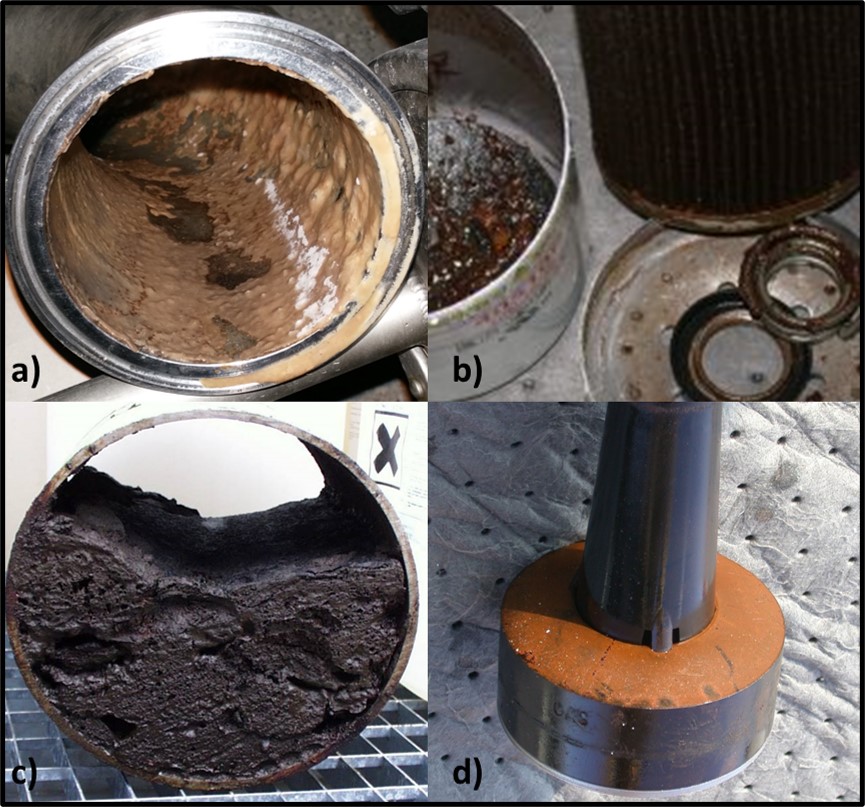
Fig 1. Biofouling – a) Fermenter transfer line; b) fuel dispenser filter; c) MWF used fluid transfer line; d) underground storage tank ATG water float.
In general terms, these four photographs illustrate how biofouling can affect industrial systems. Biofilm microbes on pipe surfaces can contaminate fluids as they flow through the line. Biomass accumulations on filter media can block fluid flow. Biofilm accumulation and the interaction between biofilm polymers and metal fines can restrict fluid flow by reducing the pipe’s functional inner diameter. Biofouling on sensor surfaces can cause sensors to generate inaccurate signals.
Although the next two biofilm-related problems depend on the presence of biofouling, the mere physical presence of biofilms can degrade industrial system operations. Think of this as passive biodeterioration – microbes are not attacking surfaces.
Heat exchanger, heat exchange inhibition
Biofilms are excellent insulators. One report (Biofilm effects on heat transfer of heat exchangers) estimated that a 5 µm thick biofilm can reduce heat exchange across copper tubes, in tube-in-shell heat exchangers, by 67 %. Tube-in-shell heat exchangers are fabricated by placing a tube bundle (Figure 2a) into an outer shell (Figure 2b). The water to be cooled either flows through the outer shell and the cooling water flows through the tubes or the cooling water flows through the outer shell and the water to be cooled flows through the tubes. Either way, the tremendous surface area to volume ratio facilitates heat transfer from the warmer fluid to the cooler fluid. The tubes are commonly made of aluminum, brass, copper, carbon steel, or stainless steel, although other metals are also used. Figures 3a and 3b respectively show heat exchanger biofouling on the exterior and interior tube surfaces. The heavy biofilms depicted in these photographs can reduce heat transfer by > 90 %.
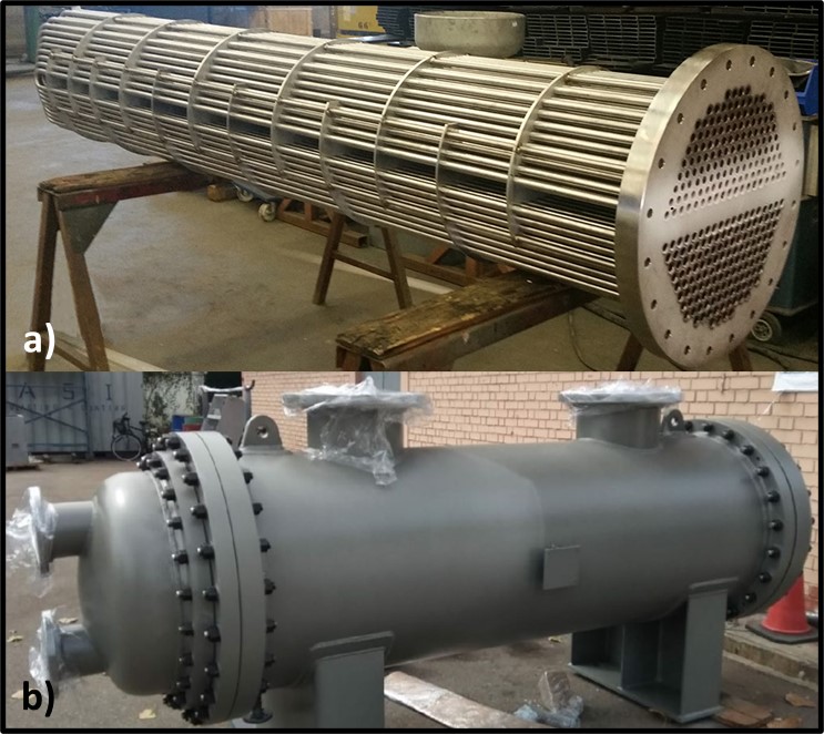
Fig 2. A tube-in-shell heat exchanger – a) tube bundle; b) outer shell.
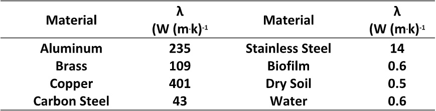
Thermal conductivity (λ) – expressed as W (m . K)-1, where W is watts, m is meters, and K is temperature in degrees Kelvin – is a measure of the ease with which heat is transmitted through a material. Table 1 provides a list the λ-values for common heat exchanger tube and insulating materials. Although λ is important, other factors such as corrosion and scaling resistance, and durability are considered when selecting heat exchanger materials. Note that λbiofilm is comparable to λdry soil and λwater. All are excellent insulators.
A case study, reporting the impact of a 1 mm of biofilm in a 200-ton centrifugal chiller operating at 50% load, stated that heat exchange was reduced by 35 %.
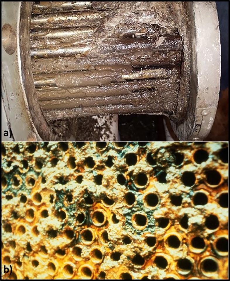
Fig 3. A tube-in-shell heat exchanger – a) biofouling coating tube exterior surfaces; b) biofouling coating tube interior surfaces.
Table 1. Selected thermal conductivity values.
As with biofouling as a general category, biofilm functionality as an insulator is a physical phenomenon – independent of microbial metabolism within the biofilm matrix.
Microbiologically influenced corrosion
Microbiologically influenced corrosion (MIC) is the biologically mediated deterioration of a material. I’ll provide a more detailed discussion of MIC in a future What’s New article. For now, I will note that MIC occurs under biofilms. Globally, MIC causes an estimated $40 billion and $100 billion U.S. damage annually. As I explained in my May 2022 article, the biofilm creates electropotential gradients including zones in which oxygen (O2) is relatively depleted. A Galvanic cell is an electrochemical cell in which an electric current is generated from oxidation-reduction reactions. The oxygen gradients within biofilms drive Galvanic oxidation-reduction reactions. As illustrated in Figure 4, an anodic cell forms under the oxygen depleted zone. Metallic iron (Fe) dissolves as ferrous iron (Fe2+) and electrons (e–) flow towards the cathodic cell (metal under more oxygen rich zones within the biofilm). Although the cathode attracts hydrogen ions (H+), dissolve oxygen (O2) can react with the hydrogen to produce water (H2O). Hydrogen removal from the cathode propagates continued electron flow and metal dissolution.
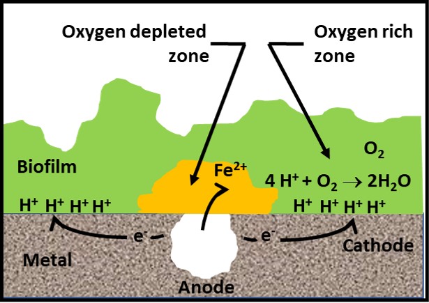
Fig 4. Galvanic corrosion under biofilm.
Galvanic corrosion can occur without direct microbial involvement, although EPS production and aerobic respiration both contribute to creating the oxygen concentration differentials illustrated in Figure 4. In fuel over water systems, biofilm accumulation is typically heaviest at the fuel-water interface (Figure 5a). The corrosion coupon shown in Figures 5a (before biofilm removal) and 5b (after coupon was cleaned for corrosion analysis) was suspended in a jar that contained diesel fuel over an aqueous salts- solution. Note that the amount of damage to the coupon was also at the interface. Although MIC tubercles can be seen on the coupon’s surface in both the interface (Figure 5c) and aqueous (Figure 5d) contact zones, the number of tubercles per cm2 is considerably greater in the interface zone. Similarly, as shown in the title photo, heaviest biofilm accumulation in MWF sumps tends to be found at the MWF-air-tank wall interface. MIC can also occur one surfaces exposed to water vapor or mist. In ships tanks, the heaviest corrosion is commonly observed on the tank overhead surfaces where water vapor condenses – providing an ideal habitat for fungal growth.
In metalworking facilities with central MWF systems, MWF returning from machines to filtration units flows through sluices. Historically, these sluices were covered with open grates. In the late 1990s grates were replaced by solid steel plates to reduce mist concentrations in facilities’ breathing zones (i.e., 1m to 2 m above the floor). This change effectively prevented mists generated in the sluice from escaping but provides a surface on which biofilms and MIC could develop (Figure 6).
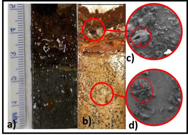
Fig 5. Corrosion coupon from fuel over water microcosm – a) biofilm-coated coupon; b) coupon after cleaning; c) scanning electron microscope (SEM) image of coupon surface at fuel-water interface (inset circle is the area analyzed by energy dispersive x-ray analysis; d) SEM image of coupon surface in zone exposed to aqueous phase.
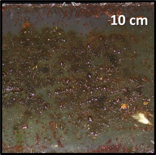
Fig 6. MWF return sluice deck plate (cover); underside.
Although biofilms and MIC develop only develop when sufficient water is present, Figure 7 illustrates how undetectable trace concentrations of water are sufficient to support MIC. Figures 7a and &b, respectively, show the exterior and interior surfaces of an UST’s submerged turbine pump’s riser. Nominally, these surfaces are in contact only with fuel. However, the exterior corrosion and innumerable tubercles on the interior surface would not have formed had they not been exposed to sufficient free water to support microbial growth.
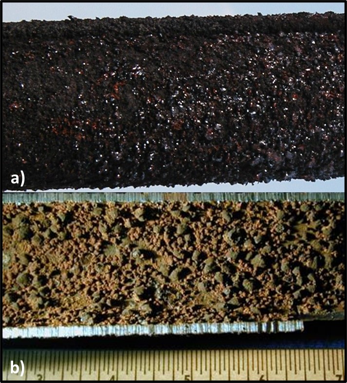
Fig 7. UST submerged turbine pump riser pipe – a) exterior surface; b) interior surface after pipe was cut in half, longitudinally.
Galvanic corrosion is only one of several MIC mechanisms. Surface depassivation (H+ ion removal) was the first MIC mechanism described. Passivation – the arrest of electron flow in a galvanic cell – occurs when the H+ ions accumulating on the cathode for a film. As part of the sulfate reduction pathway, sulfate reducing bacteria (SRB) scavenge hydrogen from a galvanic cell’s cathode. This depassivates the surface – accelerating electron flow and metal dissolution. This mechanism was reported in the 1940s before microbiologists recognized the significance of biofilms. Although SRBs are still considered to play a significant MIC role, since the 1970s it has become apparent that low molecular weight (primarily C1 – formic, C2 – acetic, and C3 – lactic acids) organic acids (LMWOA) produced by all microbes contribute to MIC. These LMWOA can react directly with metal surfaces or can react with dissolve inorganic salts such as sodium or calcium chloride to form a strong inorganic acid (hydrochloric acid – HCl) and a weak organic base (the sodium C1, C2, or C3 salt – sodium formate, sodium acetate, or sodium lactate). Strong acids such as HCl can dissolve metals aggressively. Because biofilms act as barriers, the concentration of acids at the biofilm-metal surface can quite high (e.g., 1N hydrochloric acid, 2N sulfuric acid, etc.). The pH in this high acid zone can be <2. Aggressive MIC under a biofilm can drill a hole in 1 cm think mild steel pipe or tank walls in less than six months.
Summary
Biofilms primarily contribute to three types of biodeterioration: biofouling, insulation, and corrosion. When a biofilm is present, all three types of biodeterioration can be occurring simultaneously. By creating a barrier between sensors and fluids, biofilms can cause sensor failures. Heavy biofilm accumulations can restrict fluid flow through pipes. Even thin (<5 µm) biofilms can substantially reduce heat transfer in heat exchangers. Ineffective heat exchange causes process fluid overheating and consequent fluid, system or both types of failure. MIC occurs under biofilms. Combined, these biodeterioration mechanisms cause more than $100 billion U.S. annual damage globally.
In my next What’s New article I’ll discuss general approaches for biofilm control. In the meantime, if you have any questions about the information in this post, don’t hesitate to contact me at fredp@biodeterioration-control.com.
